User Guide for Battery Charger Discharger Board Under Voltage Over Voltage Protection Module
I created a DIY 12 volt battery charger but needed a device to disconnect the battery when it reaches the desired maximum voltage. To achieve this I scouted for a circuit breaker device that could read the current voltage of the device to be disconnected. I found the ideal gadget on Ebay here.
 |
| Battery Protection Module - Connectors View |
 |
| Battery Protection Module - Top View |

At the time I bought it I had no idea it had many more uses than I needed it for. The module was deliver and thanks to the diagram in the gallery images on Ebay, I had some idea how to wire the device.

Input Power
One end (input) with only two pairs of connectors marked VIN and GND received power input to control the module (between 6 to 40 volts power source would work). In my case I used a 9 volts lithium ion battery.
 |
| 9 volt lithium battery |
Alternatively one can draw power from the device being charged like shown below
 |
| Input power taken from device being charged |
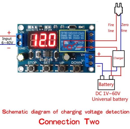
Cut-off relay terminates power to the module or supplies power to the module under specified conditions and specified settings. one can wire the module to cut-off/reconnect power on the live wire connecting to the mains (A) or cut-off/reconnect power from the charger to the battery (B).
 |
| cut-off/reconnect power on the live wire connecting to the mains (A) |
or
 |
| cut-off/reconnect power from the charger to the battery (B) |
The power from the charging source is then fed to the battery. Same wires from the battery are fed to the cut-off module according to polarity (V- and V+).
About The Module
Integrated Digital Control Accumulator Charging Module Controller Board.
Features:
Charging and discharging control for accumulators.
Auto cut-off.
Charging/discharging time setting enabled.
Real time relay work status monitoring with serial port.
With an extra signal output channel to control other devices when relay is on high level.
With STOP button and reverse plug protection.
Setting Controls:
Stop - used to cancel a setting process
set - Activates the setting mode (set voltage or module mode)
up - used to change options upwards
down - used to change options downwards
OSD/Display Symbols:
UL1: The upper limit of voltage
nL1: The lower voltage limit
OP: charging time
The upper limit of voltage is greater than the lower voltage limit (UL1>nL1).
Working Modes:
U-1: charging measurement: when the measured voltage is lower than the lower limit voltage, the relay is absorbed, higher than the upper limit voltage, and the relay is disconnected.
U-2: charge measurement time control: set the charging time (OP); when the measuring voltage is lower than the lower limit voltage, the relay will pull in and pull in, and then start the countdown OP time. When the time is up, the relay will disconnect; the relay will be cut off when the relay is higher than the upper limit voltage.
U-3: discharge detection: when the measurement voltage is lower than the lower limit voltage, the relay is disconnected, the relay is higher than the upper limit voltage, and the relay is absorbed.
U-4: discharge detection time control: set the discharge time (OP); when the measuring voltage is higher than the upper limit voltage, the relay starts to pull in and pull in, then start the countdown OP time. When the time is up, the relay disconnects; when the measuring voltage is lower than the lower limit voltage, the relay disconnects.
U-5: suction in the interval: when the measured voltage is between the upper limit and the lower limit, the relay is absorbed and the other conditions are disconnected.
U-6: interval absorption: when the measured voltage is lower than the lower limit voltage or higher than the upper limit voltage, the relay is absorbed and the other relays are disconnected.
Setting Module Up:
Connect your module to the battery (input) source or if wired to take power from the charger, plug the charger and turn it on.
Switching modes:
Press SET to display mode (e.g. U-1)
Use UP and DOWN buttons to change modes
Setting cut-off and re-connection voltage:
Setting upper-voltage-limit:
After selecting a mode e.g. U-1, press the SET button again until the LED starts to flash while displaying UL1 (upper voltage limit) and then the associated voltage.
Use the UP and DOWN buttons to set the desired upper limit voltage while the voltage number is flashing.
Setting lower-voltage-limit:
After selecting a mode e.g. U-1, press the SET button again until the LED starts to flash while displaying nL1 (lower voltage limit) and then the associated voltage.
Use the UP and DOWN buttons to set the desired lower voltage limit while the voltage number is flashing.
(Refer to mode you have chosen for desired effect).
To Activate Your settings:
When done, click on SET until the LED stops flashing


The actual calculating voltage is gloomier compared to reduce restrict voltage, the actual exchange may draw within as well as draw within, after which begin the actual countdown OP period. Once the period is actually upward, the actual exchange may detach; the actual exchange is going to Hosting Wordpress Aws be stop once the exchange is actually greater than top of the restrict voltage.
ReplyDeleteThe information that you have shared was really very useful and looks great to see and thanks for sharing the information with us.
ReplyDeletewhite label website builder
Marvelous, what a blog it is! This website provides useful data to us, keep it up. If anyone looking for practice management system in healthcare, mobile applications development company , mobile app development services in usa. I recommend Biz4Solutions LLC because they are highly skilled & are capable of handling complex projects without complicating it.
ReplyDelete